Fostex 600 repair
Repairing and consolidating a Fostex 600 audio amplifier.
Intro
I got this amplifier to be repaired.
At full power, when the device heat up, one audio channel fails.
It seems this audio amplifier is from 1979 and the building quality is very good (Japanese build).
First power-up
I know this amplifier powers-up without issues (was previously used on a swiss 10A power outlet).
So I tried to switch it on in my lab (french 16A power outlet), the main circuit-breaker of my house trip instantly.
After some toughts, I realized the amplifier as a huge toroidal transformer.
The in-rush current when the amplifier is switched on is probably too high for my 1995 circuit breaker.
This topic is largely discussed on internet. I’ll not write about the theory behind this in-rush current in this post.
Soft-starter
In order to be able to check this device in my lab, I need to figure out a way to power the amplifier on my electrical setup.
You find plenty of in-rush current limiting modules and device (on audio stores, and Aliexpress).
Basically, it will add some in series resistors during a short amount of time to allow the core of the transformer to be magnetized.
After this short period of time, a relay will shunt these resistors and the soft-start circuit will not limit current anymore.
There are some designs using thermistors in place of simple resistors, I think they are better because the current will slowly increase when the thermistor temperature increase (negative coefficient).
Fortunatly, I already encounter this in-rush issue at work (with some stepper drivers, powered by a huge transformer).
We found a company FSM specialized in this soft-starters devices (we use TSRL) and some remains in our stock.
So I’m not able to soft-start the amplifier without any in-rush current on my electrical installation.
My plan is to directly integrate this module inside the amplifier.
Repairs and upgrade
Replacing capacitors
I got my hands on two 22000uF/100V capacitors with the same dimensions of the original 18000uF/100V capacitors (C851 and C852).
Even if the measured capacitance of the old ones are in tolerance, it can be good to replace them.
Replacing these two capacitors is not a huge task, but the new capacitors I get have a slight bigger screw.
I remade some terminals because the hole in the original wiring is too small.
Replacing transistors
To be done, check them and replace…
According to HowardJohnstone, some transistors should be replaced to avoid transistors breakage.
Please consider replacement of TR607/608 pair and bias pair TR605/606 with
KSA1142/KSC2682 respectively at sight. This is an accident waiting to happen.
Also consider replacing the small TR603/604 (TO92) with KSA1013 transistor.
The clip-on heatsink is also to small and must be upgraded to a proper one.
These amps (300) where designed around available transistors at the time, thus
the very close tolerance to 150V. But today we have 230VAC and thus 160V!I have repaired several (only 300s) amps with all the same burnt out channels.
(Burnt out PCB traces, drivers and output devices, a lot of work to reconstruct.)A simple and basic amp of high quality, but bordering on the “voltage” edge.
Well worth upgrading (and please do this) as today high voltage trans are
easily available at low cost.
Cleaning potentiometers
To be done.
Adjusting bias
To be done.
Testing
I need to find a 8 ohm load strong enough to get the full amplifier power (300W per channel!).
Pictures
Here are some pictures of the work done.
Power part (the big round part is the transformer), the two big capacitors are 18000uF/100V capacitors.
The green PCB on top is the LED vu-meter circuit. We can also see the two volume control knobs.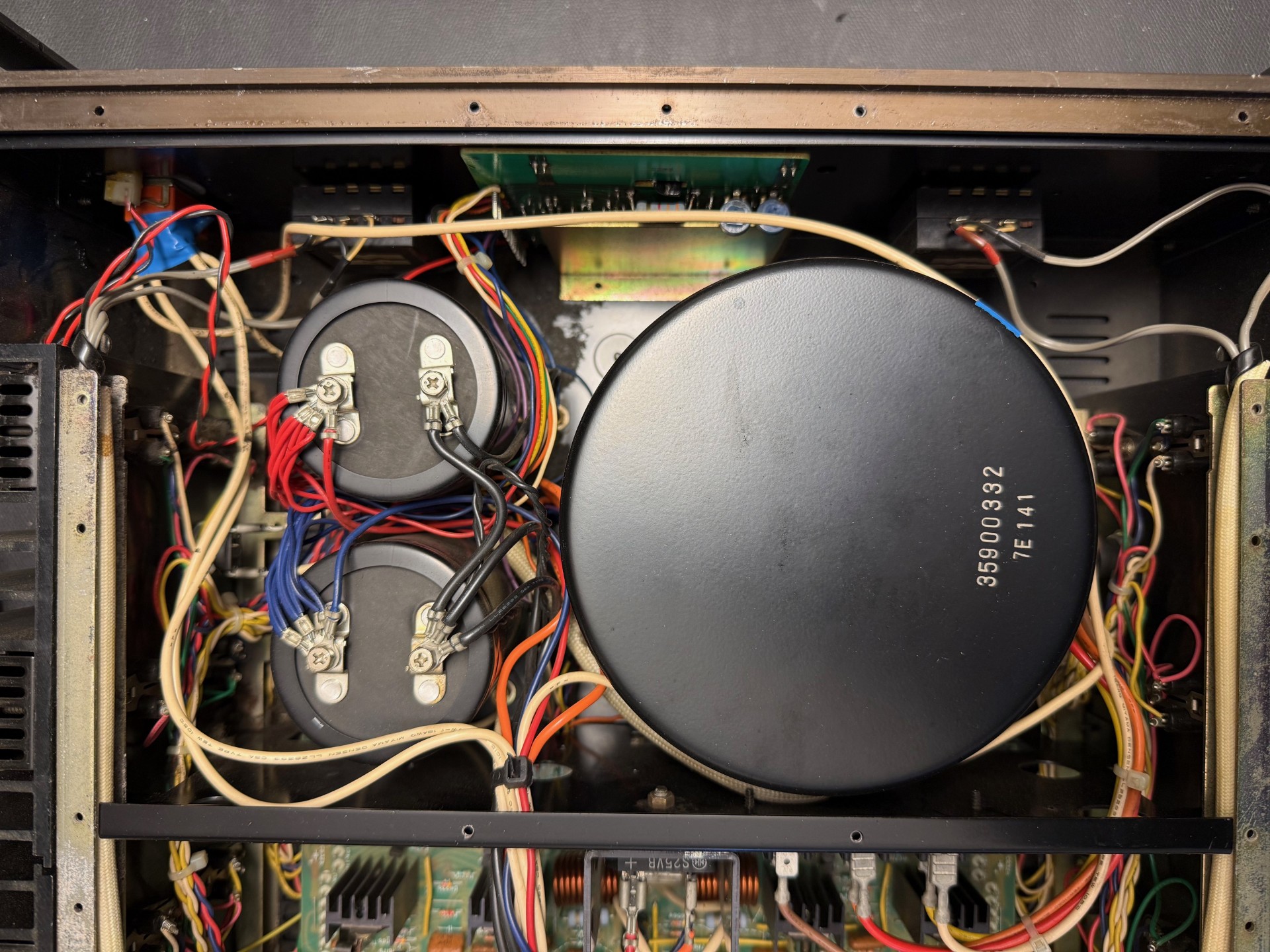
Links
Some advices to replace transistors to support higher voltage.
Interresting discussion about transistors overheating
Bias drifting discussion
Service manual